+44 (0) 20 3858 0833
 email
email

Tube Noise Soundproofing London:
London Underground Train Noise & Vibration Control / Clapham, London – read more…
Please read on or visit the dedicated website: www.mutetube.co.uk
Client
Private residence, Clapham, London
Circumstances
The project involved a three-storey, mid-terrace Victorian house (of traditional masonry construction), located in a residential area of Clapham, South London.
Northern Line London Underground trains run between Clapham South and Balham stations nearby, with the nearest section of track approximately 290 metres away.
Having lived at the property since 1994, the client had not been disturbed by underground train noise, until relatively recently (summer 2018), when trains became significantly louder, particularly in the living room and connecting hallway; possibly as a consequence of TfL re-opening the Clapham South deep-level shelter as a tourist attraction in spring/summer 2016.
In both spaces, the floor was of suspended timber construction, consisting of 17 mm timber floorboards, supported on 105 mm timber joists, further supported on 50 mm timber battens on brick pillars. The total void depth between the underside of the floorboards and the concrete substrate was approximately 275 mm.
Project Brief
To design and install a system of remedial works to the living room and connecting hallway, to adequately reduce groundborne noise and vibration emanating from the passing trains, in accordance with Noise & Vibration Asset Design Guidance, published by Transport for London (TfL), which states that:
“The noise from sub surface underground railways should not be considered to be significant if the groundborne noise as measured in a residential dwelling does not give rise to an average maximum noise level exceeding 40 dB, LAFmax. This is based on an assessment of at least 10 trains for the line being assessed.”
It goes on to say:
“In recognition that the sensitivity of people to noise can vary significantly the designers should use reasonable endeavours to meet a more stringent requirement of 35 dB, LAFmax.“
These guidelines are in general agreement with the conclusions of groundborne noise studies in the USA, published by the American Public Transit Association (APTA) and the Federal Transit Administration (FTA).
Notably, having conducted an initial investigation, TfL acknowledged “significant” tube noise at the property, but asserted (having also assessed the condition of the train track) that the noise experienced was not as a result of track degradation. As such, they concluded that no noise and vibration remedial works could be carried out at that time.
Accordingly, without the option of corrective works at source (which is preferable, in the first instance), the client sought an interior solution.
Methodology
1. Site Survey/Underground Tube Noise & Vibration Testing:
The first step in specifying a system of remedial works was to conduct a schedule of groundborne noise and vibration (A.K.A. underground tube noise) testing, with a view to establishing three critical details:
- The average maximum groundborne noise levels generated by the passing trains, to be cross referenced against Noise & Vibration Asset Design Guidance, to determine the levels of attenuation required to conform to the recommended standards.
- The sound frequencies, generated by the passing trains, most integral to the average maximum groundborne noise levels, to determine the correct natural resonant frequency of the remedial system, in order to achieve attenuation, i.e. if incorrectly specified, unity gain or, in the worst case scenario, amplification may occur.
- The structural surfaces through which the sound producing vibrations, generated by the passing trains, most prominently radiated, to determine where remedial works should be focused, to optimise attenuation.
Additionally, testing would record the prevailing background sound levels, during no train pass-bys, to determine the average sound level differential between the two events; serving as a useful point of reference, i.e. assuming frequency parity, the narrower the margin, the less perceptible the train noise becomes.
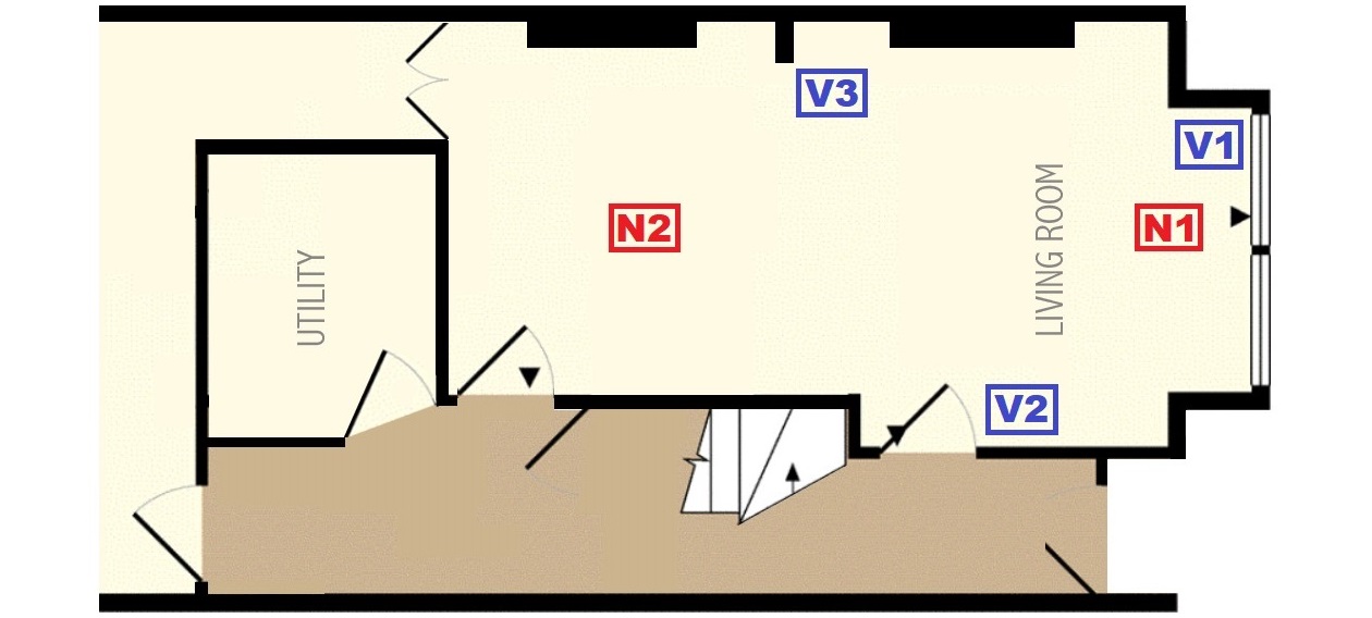
The floor plan below shows the test positions selected inside the living room, with those denoted with an ‘N’ representing groundborne noise and vibration testing (specifically at floor level) and those denoted with a ‘V’ representing vibration testing only.
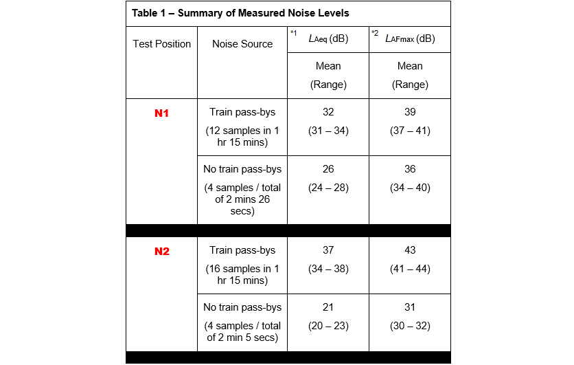
*1 LAeq is a measure of the acoustic energy of a fluctuating noise climate over a given period of time. The ‘A’ within the descriptor means A-weighted, an internationally agreed frequency response, generally similar to that of the human ear, so that A-weighted sound levels in dB correspond reasonably well with what is heard.
*2 LAFmax represents the maximum reading given by a sound level meter for a given event or period of time.
2. Assessment of Underground Tube Noise Pre-Works Test Data:
In terms of the groundborne noise levels generated by the passing trains, as per Table 1, the highest levels were measured at test position N2 (rear living room), with a mean, from 16 train pass-bys, of 37 dB, LAeq and 43 dB, LAFmax. Notably, the LAFmax figure was 3 dB higher than the TfL guidance, confirming that the noise generated in this area was “significant”, by their standards.
At test position N1 (front living room), groundborne noise levels were lower, with a mean, from 12 train pass-bys, of 32 dB, LAeq and 39 dB, LAFmax. As such, whilst the LAFmax figure would not be considered “significant”, it was a substantial 4 dB higher than the TfL document’s more stringent design target of 35 dB, LAFmax. Moreover, at the time of testing (weekday afternoon), train noise, at both positions, was between 6 dB (N1) and 16 dB (N2) above the prevailing background sound levels (in terms of LAeq), notably contributing to overall audibility.
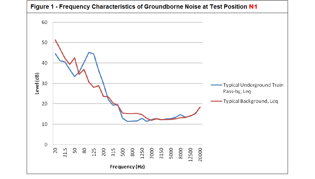
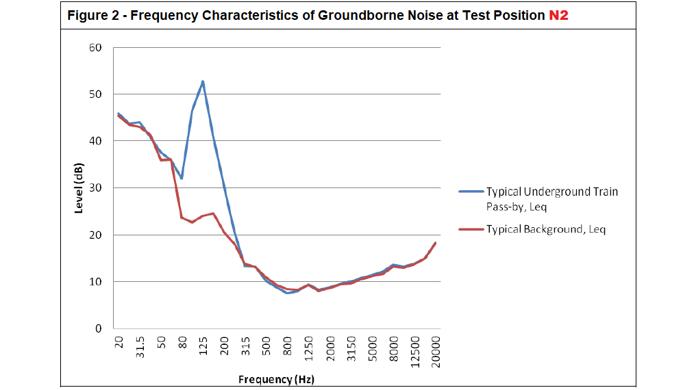
In terms of the sound frequencies, generated by the passing trains, as per Figure 1 and 2, strong peaks were measured at test position N1 and N2 in the 125 Hz and 160 Hz frequency bands (characterised by a low frequency ‘rumbling’). This was particularly pronounced at N2, where sound levels were measured at c.53 dB (compared with c.45 dB at N1), approximately 30 dB higher, in these frequency bands, than the prevailing background sound levels.
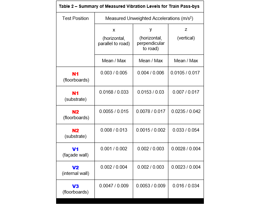
Finally, in terms of the surfaces through which the sound producing vibrations, generated by the passing trains, most prominently radiated, as per Table 2, this was measured at position N2, in the ‘z’ (vertical) direction, from the substrate (0.054 m/s2 (max)). The vertical vibration levels on the floorboards, directly above, measured only slightly lower (0.042 m/s2 (max)), suggesting that most of the ground vibrations were being transferred to the timber floorboards.
The third highest measurement was recorded at position V3, in the ‘z’ (vertical) direction (0.034 m/s2 (max)). Closely followed at position N1, in the ‘x’ and ‘y’ horizontal direction, from the substrate (0.033 m/s2 (max) and 0.03 m/s2 (max), respectively). Curiously, at N1, the vibration levels on the timber floorboards, directly above the substrate, were much lower in the horizontal axes (0.005 m/s2 (max) and 0.006 m/s2 (max), respectively), whilst, in the vertical axes, they were less surprisingly similar. The vibration levels measured at position V1 and V2, in all axes, were only just above background vibration.
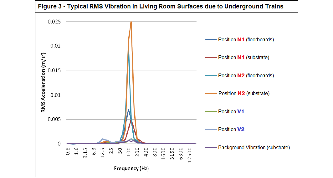
Critically, as per Figure 3, all of the test positions had a peak in vibration levels in the 125 Hz and 160 Hz frequency bands, corresponding with the peaks in groundborne noise, as per Figure 2 and 3, strongly supporting the assumed correlation between the vibrations in the floor and the generated noise.
3. Design & Installation of Underground Tube Noise Solution (Phase 1 – Rear Living Room):
In light of the test data, in particular, how the rear living room floor was so clearly the primary contributor, in terms of measurable groundborne noise and vibration, coupled with the inherent complexities in accurately calculating performance projections, it was decided that the project should be broken down into two phases.
Phase 1 – to design and install a system of remedial works to the rear living room floor, which, on completion would be tested to demonstrate its efficacy, in relation to TfL’s Noise & Vibration Asset Design Guidance; such that average maximum noise levels would not exceed 40 dB, LAFmax, with the more stringent design requirement of 35 dB, LAFmax, serving as the optimal result.
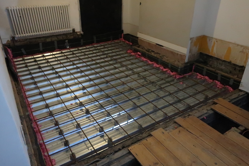
Image showing acoustic floating floor system, installed in rear living room, ready for concrete pour.
4. Pre-Completion Testing of Underground Tube Noise Solution (Phase 1 – Rear Living Room):
The floor plan below shows the post-works test positions selected inside the rear living room, with each position the focus of groundborne noise and vibration testing.
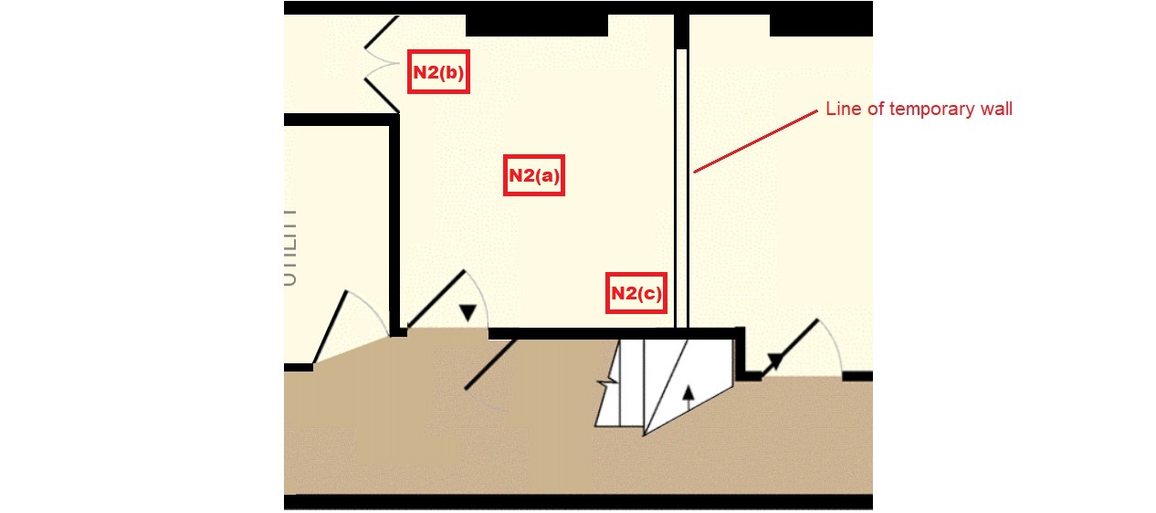
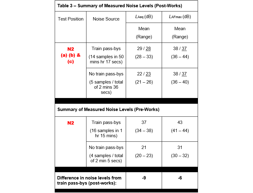
For the purpose of testing, the rear living room was separated from the front living room by a temporary plasterboard partition, to isolate the sound levels being measured, from the adjoining, untreated spaces. However, this gave rise to higher reverberation times than would typically be found in a living room, i.e. being comprised of entirely hard, reflective surfaces, with no soft furnishings. Accordingly, reverberation time measurements were made in the rear living room area, using a reference reverberation time of 0.5 seconds for a ‘typical’ furnished living room, providing a correction of -1 dB(A). The corrected values are underlined in Table 3.
5. Assessment of Underground Tube Noise Pre-Completion Test Data (Phase 1 – Rear Living Room):
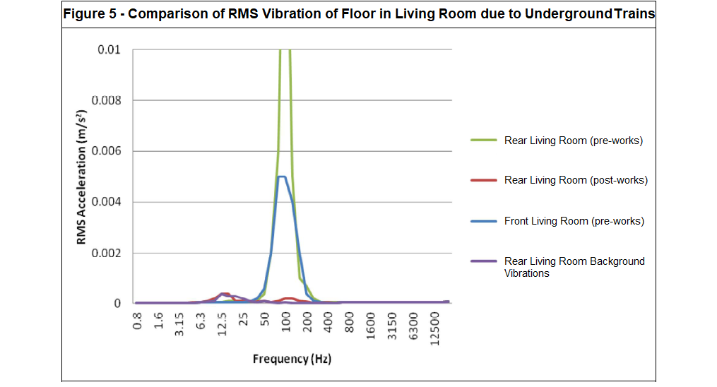
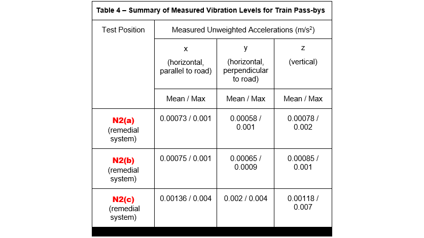
In terms of the vertical vibration levels, due to underground train pass-bys, measured from the treated floor, compared with the original suspended timber floor, it can be seen, from Figure 5, that the peak in the 125 Hz and 160 Hz 1/3 octave bands has been very effectively controlled, with a reduction by a factor of between 10 and 25. A similar reduction can also be seen in the ‘x’ and ‘y’ axes, as per Table 4.
(It should be noted that the vertical levels in the treated floor, as per Table 4, are significantly lower than the equivalent horizontal vibration (into the room) of the walls, as per Table 2. This is likely to mean that the residual groundborne noise levels in the rear living are now controlled by noise generated by vibration of the walls, rather than of the floor. Accordingly, the walls would be next-in-line for treatment, should further remediation be required).
Subsequently, in terms of the sound levels now measured in the rear living room, as per Table 3, it can be seen that a mean reduction of 9 dB, LAeq and 6 dB, LAFmax has been achieved. As such, TfL would conclude that the noise “should not be considered to be significant”, with the level just 2 dB short of their more stringent design target of 35 dB, LAFmax.
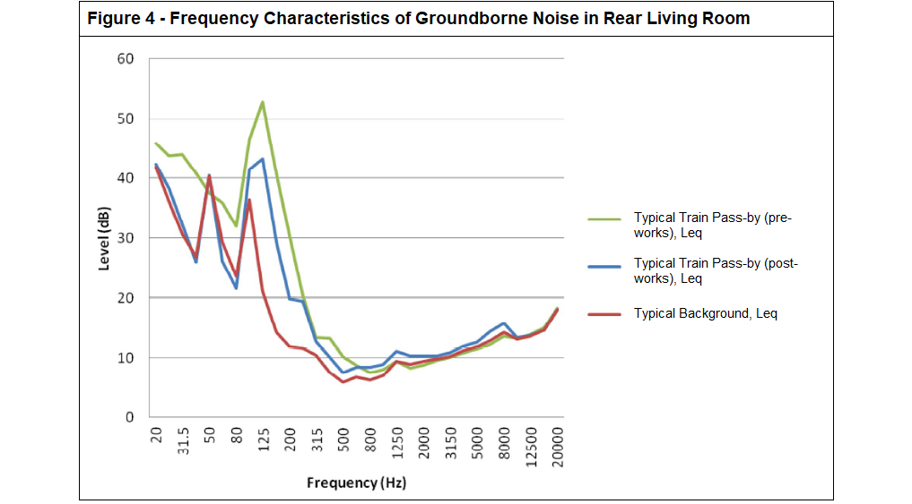
Moreover, as per Figure 4, it can be seen that, across the frequency range 63 Hz to 200 Hz, i.e. those frquencies most integral to the radiated train noise, sound levels have been reduced by between 6 and 10 dB.
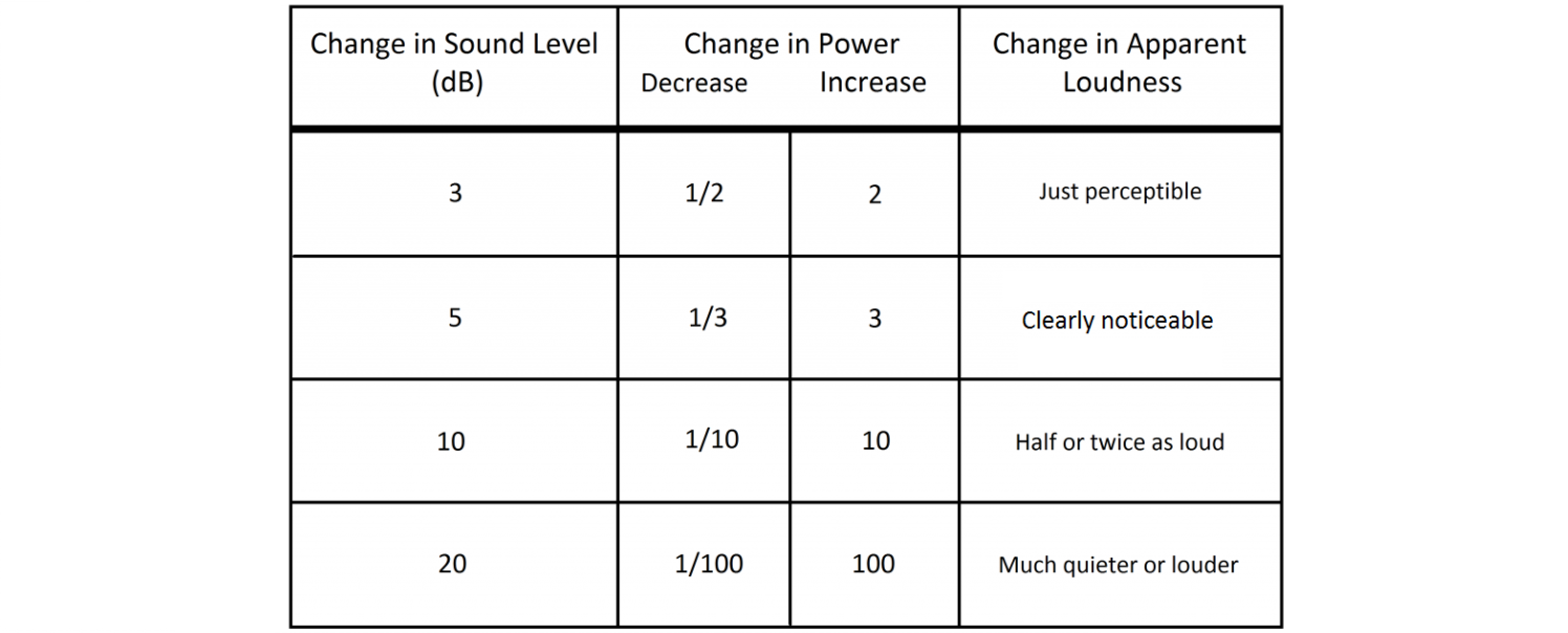
The table below, as published in Prof. Colin H. Hansen’s ‘Fundamentals of Acoustics’, provides a practical point of reference for understanding the aforementioned attenuation levels.
6. Design & Installation of Underground Tube Noise Solution (Phase 2 – Front Living Room & Connecting Hallway):
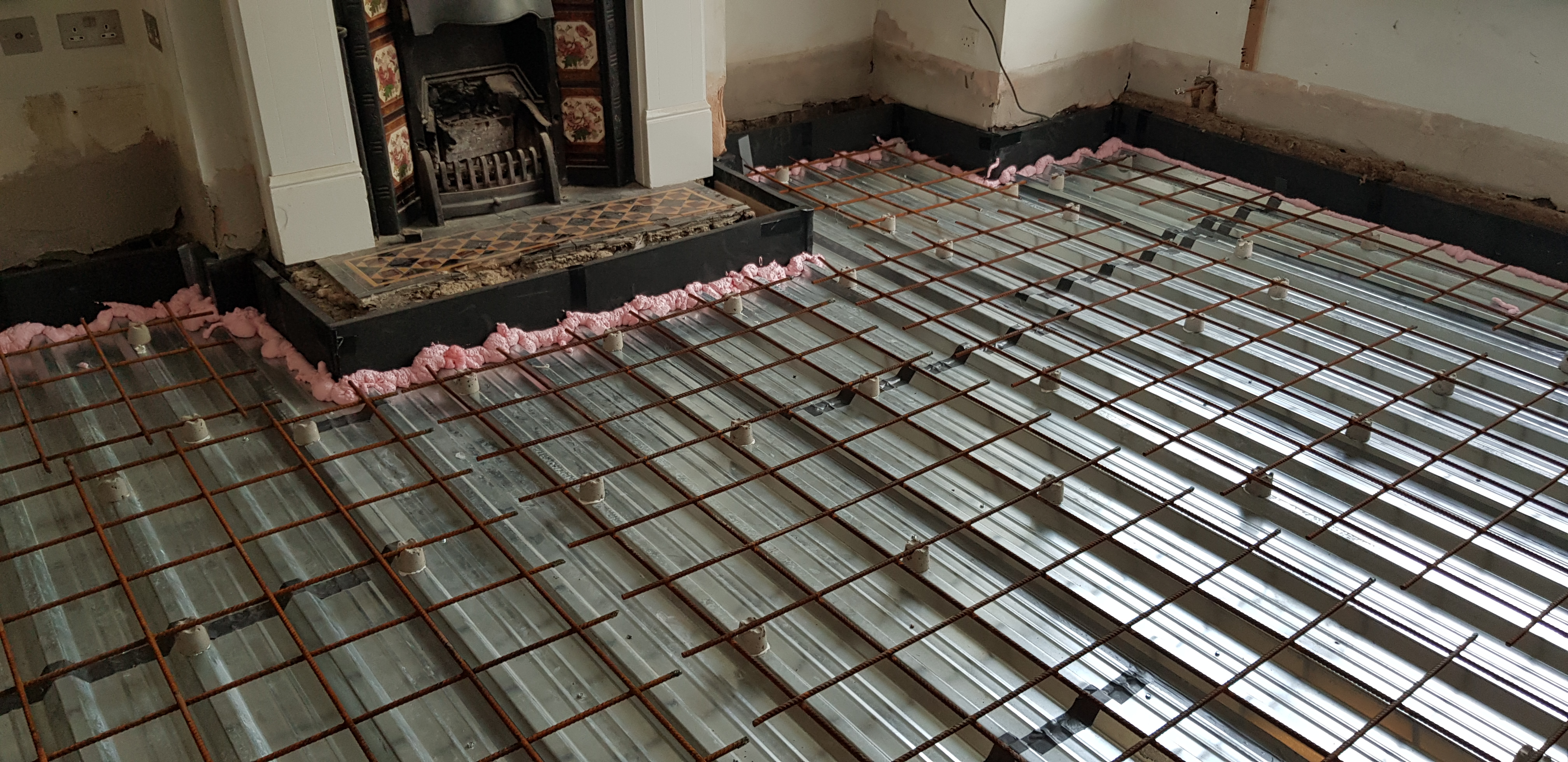
Image showing acoustic floating floor system, installed in front living room, ready for concrete pour.
7. Pre-Completion Testing of Underground Tube Noise (Front & Rear Living Room):
Test data coming soon.
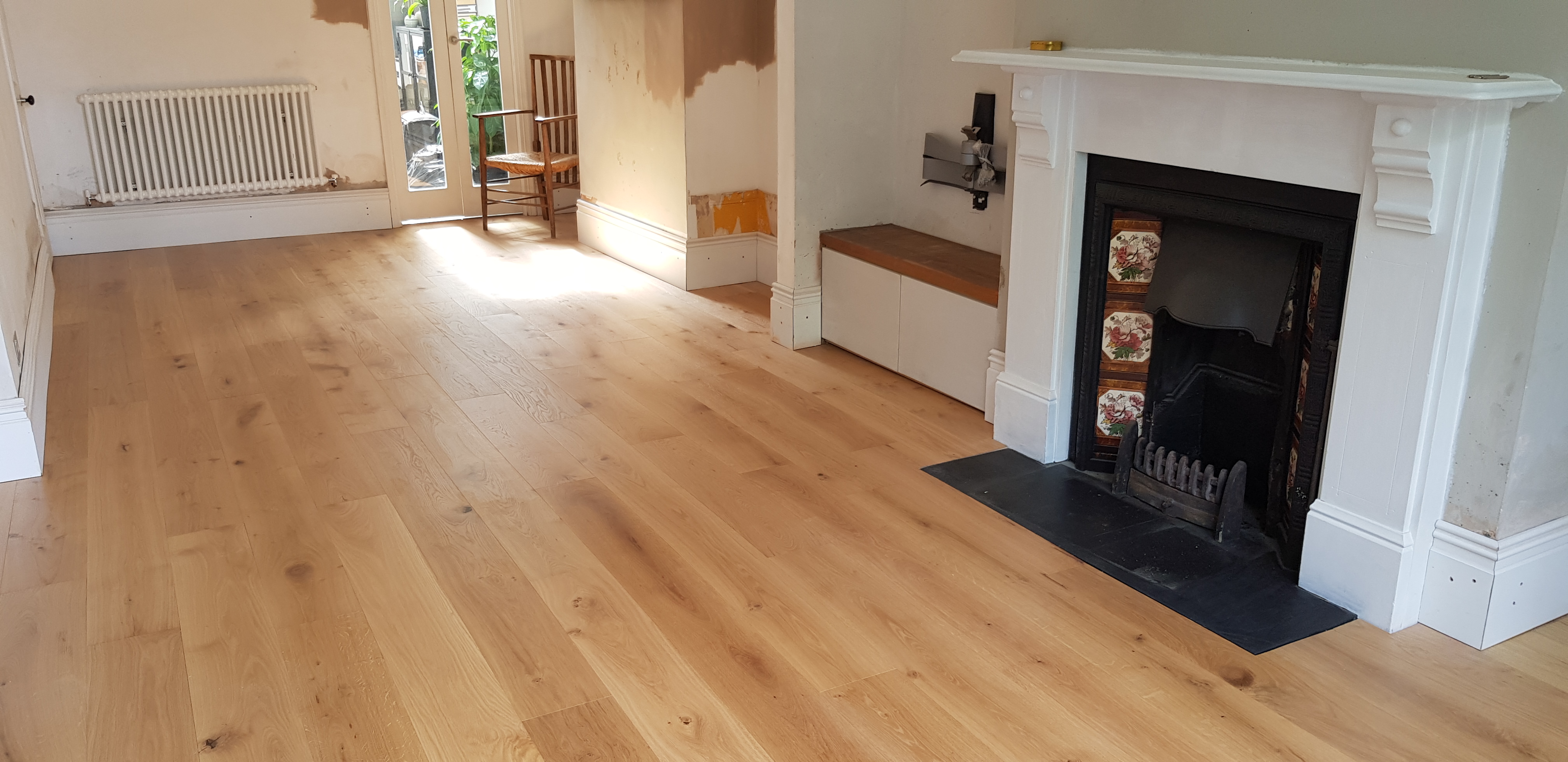
Image showing engineered timber floor, installed atop completed acoustic floating floor system. Living room now ready for decorative works.
Visit Mute Tube® to view more London Underground train noise & vibration control case studies.